Pulse power supply How to make a switching power supply with your own hands? Power sides on diagram DA1
Many electrical devices have long been using the principle of realizing secondary power through the use of additional devices, which are entrusted with the functions of providing electricity to circuits that require power from certain types of voltage, frequency, current...
For this purpose, additional elements are created: converting voltage of one type to another. They can be:
built inside the consumer case, as on many microprocessor devices;
or made in separate modules with connecting wires similar to a conventional mobile phone charger.
In modern electrical engineering, two principles of energy conversion for electrical consumers, based on:
1. using analog transformer devices to transfer power to the secondary circuit;
2. switching power supplies.
They have fundamental differences in their design and operate using different technologies.
Transformer power supplies
Initially, only such designs were created. They change the voltage structure due to the operation of a power transformer, powered from a 220-volt household network, in which the amplitude of the sinusoidal harmonic decreases, which is then sent to a rectifier device consisting of power diodes, usually connected in a bridge circuit.
After this, the pulsating voltage is smoothed out by a parallel-connected capacitance, selected according to the permissible power, and stabilized by a semiconductor circuit with power transistors.
By changing the position of the trimming resistors in the stabilization circuit, it is possible to regulate the voltage at the output terminals.
Switching power supplies (UPS)
Similar design developments appeared en masse several decades ago and became increasingly popular in electrical devices due to:
availability of common components;
reliability in execution;
possibilities to expand the operating range of output voltages.
Almost all switching power supplies differ slightly in design and operate according to the same scheme, typical for other devices.

The main parts of power supplies include:
a network rectifier assembled from: input chokes, an electromechanical filter that provides noise rejection and static isolation from capacitors, a network fuse and a diode bridge;
storage filter tank;
key power transistor;
master oscillator;
feedback circuit made using transistors;
optocoupler;
a switching power supply, from the secondary winding of which voltage emanates to be converted into a power circuit;
rectifier diodes of the output circuit;
output voltage control circuits, for example, 12 volts with adjustment made using an optocoupler and transistors;
filter capacitors;
power chokes that perform the role of voltage correction and diagnostics in the network;
output connectors.
An example of an electronic board of such a switching power supply with a brief designation of the element base is shown in the picture.

How does a switching power supply work?
The switching power supply produces a stabilized supply voltage by using the principles of interaction between the elements of the inverter circuit.
The 220 volt network voltage is supplied through the connected wires to the rectifier. Its amplitude is smoothed by a capacitive filter through the use of capacitors that can withstand peaks of about 300 volts, and is separated by a noise filter.
12V switching power supplies are increasingly used in everyday life today. With their help, various types of batteries are charged, some types of lighting are implemented, even uninterruptible power supply for computer and other networks. Of course, the easiest way to get the necessary switching power supply is to buy it in a store. For example, a switching power supply based on tl494.
But we are interested in the possibility of assembling this device with our own hands. So, switching power supply - diagram, details and recommendations for its assembly.
If we consider the block diagram, it consists of four elements:
- Network rectifier.
- Voltage rectifier.
- Control system.
The structure of the power supply is shown in the bottom figure.

So, what functions does each of these elements perform? The mains rectifier converts alternating current into direct current. That is, the voltage ripple is smoothed out. A high-frequency converter, on the contrary, converts direct voltage into alternating voltage. In this case, the shape of the pulses becomes, firstly, rectangular, and secondly, with the required amplitude.
The voltage rectifier partially smooths out the voltage. By the way, in some power supplies this element is absent; the electric current flows directly to the smoothing filter, which is connected to the load with its output. The diagram shows that the control system is connected to both a high-frequency converter and a voltage rectifier. The thing is that the VChP control occurs due to feedback from the rectifier.
This block diagram of a simple 12V switching power supply, by the way, has a large number of critics who claim that its efficiency is quite small. In principle, this is the case, but if you correctly select all the elements, if you carry out the calculations correctly, then switching power supplies of this type will have an efficiency of at least 90%. And this already means something.

Schematic diagrams
So, the basis for assembling a switching power supply is not only the circuit diagram, or rather, its reasonable choice, but also the choice of its main elements. In principle, in this case it is necessary to accurately select two elements:
- Voltage rectifier.
We will talk about them.
In fact, this long name can be replaced with a short one - inverter. It can be single- or two-stroke, which uses a pulse transformer. Here are some diagrams of this element:
 High frequency converter circuit
 The simplest circuit, in which only a transformer is installed, is single-ended (first position). It is simplicity that creates some disadvantages:
- It is necessary to install a large transformer because this device operates on a private hysteresis loop.
- In order for the output current power to be large, it is necessary to increase its pulse amplitude.
Therefore, this circuit is most often used in power supplies for low-power devices, where the influence of these shortcomings will not affect the operation of the device itself.
The second position is a push-pull circuit, which is called push-pull. There are no disadvantages of single-cycle, but it also has its disadvantages: increased requirements for the maximum voltage value of the switches and a more complex design of the transformer itself.

The third position is a push-pull half-bridge. In fact, this is the previous model only with a simplified transformer. It is this criterion that has become the basis of switching power supplies, which are used for electrical appliances with a power of no more than 3 kW.
The fourth position is a bridge switching power supply. It doubles the number of power switches, which makes it possible to increase power. And this is beneficial both from a technical and economic point of view.
Transformer selection
The switching power supply, or more precisely, its power, will depend on the selected type of transformer core. For power supplies up to 1 kW, a transformer with a ferrite core is installed.
Attention! It must be remembered that in transformers with a ferrite core large voltage losses occur if its frequency approaches 100 Hz.
Voltage rectifier
There are three main voltage rectification schemes with a nominal value of 220 volts.
- Half-wave.
- Full-wave.
- Zero or, like the previous one, only with a midpoint.

The first circuit is the simplest, which uses a minimum number of semiconductor elements. Its only drawback is the high voltage ripple at the output. Although it would be possible to add a small rectification coefficient (0.45), therefore, using this circuit, you will have to install a powerful filter.
Zero has a high rectification coefficient of 0.9. True, in this case it is necessary to almost double the number of rectification diodes. The disadvantage is the presence of a network transformer. That is, its overall dimensions have little to do with the concept of small-sized devices, especially when it comes to a switching power supply.
The third position is the same as the second, only without a transformer. It is replaced by a capacitive filter, which has its drawback - a high output current pulse. True, this drawback is not critical.

Conclusion on the topic
As you can see, the circuit diagram for switching power supplies has several varieties. But for each of them to work correctly, it is necessary to select its components correctly. Of course, all this is not as simple as it might seem at first glance, but if you take into account our recommendations, you can independently assemble a small power unit, for example, to illuminate rooms with LED lamps.
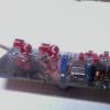
Switching power supply 180W
The power of the power supply is about 180 W, the output voltage is 2x25 V at a load current of 3.5 A. The ripple range at a load current of 3.5 A does not exceed 10% for a conversion frequency of 100 Hz and 2% for a frequency of 27 kHz. The output impedance does not exceed 0.6 Ohm. Block dimensions - 170x80x35 mm; weight - 450 g.
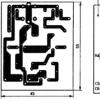
After rectification by the diode bridge VD1, the mains voltage is filtered by capacitors C1-C4 (see diagram). Resistor R1 limits the charging current of the filter capacitors flowing through the rectifier diodes when the unit is turned on. The filtered voltage is supplied to a voltage converter built according to a half-bridge inverter circuit using transistors VT1, VT2. The converter is loaded with the primary winding of transformer T1, which converts the voltage and galvanically isolates the output of the unit from the AC mains. Capacitors C3 and C4 prevent RF interference from the power supply from entering the network. A half-bridge inverter converts direct voltage into rectangular alternating voltage with a frequency of 27 kHz. Transformer T1 is designed so that its magnetic circuit is not saturated. The self-oscillating mode of operation is ensured by a feedback circuit, the voltage of which is removed from winding III of transformer T1 and supplied to winding I of auxiliary transformer T2. Resistor R4 limits the voltage on winding I of transformer T2. The conversion frequency depends within certain limits on the resistance of this resistor (see note at the end of the page). You can read in detail about the operation of converters with a non-saturable transformer in.
To ensure reliable startup of the converter and its stable operation, a startup unit is used, which is a relaxation generator based on a VTZ transistor operating in avalanche mode. When the power is turned on, capacitor C5 begins to charge through resistor R5 and when the voltage across it reaches 50...70 V, transistor VTZ opens like an avalanche and the capacitor is discharged. The current pulse opens transistor VT2 and starts the converter.
Transistors VT1 and VT2 are installed on heat sinks with an area of 50 cm2 each. Diodes VD2-VD5 are also equipped with plate heat sinks. The diodes are sandwiched between five duralumin plates measuring 40x30 mm each (the three middle plates are 2 mm thick, the two outer ones are 3 mm thick). The entire package is tightened with two M3x30 screws passed through the holes in the plates. To prevent the plates from being closed by screws, pieces of polyvinyl chloride tube are placed on them.
The winding characteristics of transformers are summarized in the table.
|
Transformer |
Number of turns |
Magnetic core |
||
|
Ferrite 2000NN, two rings K31x18.5x7 glued together |
||||
|
Ferrite 2000NN, ring K10x6x5 |
||||
Winding wire - PEV-2. Winding I is placed evenly along the length of the ring. To facilitate starting the converter, winding III of transformer T1 should be located in a place not occupied by winding II (see figure). Inter-winding insulation in transformers is made with varnished fabric tape. Between windings I and II of transformer T1 there is three-layer insulation, between the remaining windings of transformers it is single-layer.
Capacitors C3, C4 in the block - K73P-3; C1, C2 - K50-12; C5 - K73-11; S8,S9 - KM-5; C6, C7 -- K52-2. Transistors KT812A can be replaced with KT812B, KT809A, KT704A-KT704V, diodes KD213A with KD213B.
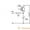
A correctly assembled power supply usually does not need adjustment, but in some cases it may be necessary to select a VT3 transistor. To check its functionality, temporarily disconnect the emitter output and connect it to the negative terminal of the network rectifier. The voltage on capacitor C5 is observed on the oscilloscope screen - a sawtooth signal with a swing of 20...50 V and a frequency of several hertz. If there is no ramp voltage, the transistor must be replaced.
The use of this power source does not eliminate the need to block the output power circuits of the amplifier with large capacitors. Connecting such capacitors further reduces the ripple level.
Literature
1. V. Tsibulsky Economical power supply. Radio, 1981, No. 10, p. 56.
2. Romash E. M. Sources of secondary power supply for radio-electronic equipment. - M.: Radio and Communications, 1981.
3. Biryukov S. Digital frequency meter power supply, - Radio. 1981. No. 12, p. 54, 55.
D. BARABOSHKIN
Radio, 6/85
NOTE
When turning on the power supply, measure the conversion frequency (at the terminals of winding II) - it may be significantly lower than 27 kHz (for example, 9 - 12 kHz). And although the device will work, the power transistors will fail due to overheating. Frequency adjustment is carried out by resistor R4. Moreover, the rating may differ from that indicated on the diagram by tens of ohms.
A correctly configured power supply works great; at a load of 50 - 70%, the power transistors remain cold.

The sound quality depends almost as much on the parameters of the power source as on the amplifier itself, and you should not be negligent in its manufacture. There are more than enough descriptions of calculation methods for standard transformers. Therefore, here is a description of a switching power supply that can be used not only with amplifiers based on the TDA7293 (TDA7294), but also with any other 3H power amplifier.
The basis of this power supply unit (PSU) is a half-bridge driver with an internal oscillator IR2153 (IR2155), designed to control MOSFET and IGBT technology transistors in switching power supplies. The functional diagram of the microcircuits is shown in Figure 1, the dependence of the output frequency on the ratings of the RC-drive chain in Figure 2. The microcircuit provides a pause between the pulses of the “upper” and “lower” switches for 10% of the pulse duration, which allows you not to worry about “through” currents in the power part of the converter.

Rice. 1

Rice. 2
The practical implementation of the power supply is shown in Figure 3. Using this circuit, you can make a power supply with a power from 100 to 500 W, you only need to proportionally increase the capacitance of the primary power filter capacitor C2 and use the corresponding power transformer TV2.
Rice. 1
The capacitance of capacitor C2 is selected at the rate of 1...1.5 µF per 1 W of output power, for example, when manufacturing a 150 W power supply, a capacitor of 150...220 µF should be used. The VD primary power supply diode bridge can be used in accordance with the installed primary power supply filter capacitor; with capacitances up to 330 µF, 4...6 A diode bridges can be used, for example RS407 or RS607. With a capacitor capacity of 470... 680 μF, more powerful diode bridges are needed, for example RS807, RS1007.
We can talk about the manufacture of a transformer for a long time, but not everyone needs to delve into the deep theory of calculations for too long. Therefore, calculations according to Eranosyan’s book for the most popular standard sizes of ferrite rings M2000NM1 are simply summarized in Table 1.
As can be seen from the table, the overall power of a transformer depends not only on the dimensions of the core, but also on the conversion frequency. It is not very logical to make a transformer for frequencies below 40 kHz - harmonics can create insurmountable interference in the audio range. The manufacture of transformers for frequencies above 100 kHz is no longer permissible due to self-heating of the M2000NM1 ferrite by eddy currents. The table shows data on the primary windings, from which the turns/volt ratios can be easily calculated, and then it will not be difficult to calculate how many turns are needed for a particular output voltage. It should be noted that the voltage supplied to the primary winding is 155 V - the mains voltage of 220 V after the rectifier and smoothing filter will be 310 V DC, the circuit is semi-bridged, therefore half of this value will be applied to the primary winding. It should also be remembered that the shape of the output voltage will be rectangular, therefore, after the rectifier and smoothing filter, the voltage value will not differ significantly from the calculated one.
The diameters of the required wires are calculated from a ratio of 5 A per 1 sq mm of wire cross-section. Moreover, it is better to use several wires of smaller diameter than one, thicker wire. This requirement applies to all voltage converters with a conversion frequency above 10 kHz, since the skin effect - losses inside the conductor - is already beginning to affect, since at high frequencies the current no longer flows across the entire cross-section, but along the surface of the conductor, and the higher the frequency, the stronger the effect losses in thick conductors. Therefore, it is not recommended to use conductors thicker than 1 mm in converters with conversion frequencies above 30 kHz. You should also pay attention to the phasing of the windings - incorrectly phasing windings can either damage the power switches or reduce the efficiency of the converter. But let’s return to the power supply shown in Figure 3. The minimum power of this power supply is practically unlimited, so you can make a power supply with 50 W or less. The upper power limit is limited by certain features of the element base.
To obtain higher powers, more powerful MOSFET transistors are required, and the more powerful the transistor, the greater the capacitance of its gate. If the gate capacitance of the power transistor is quite high, then a significant current is required to charge and discharge it. The current of the IR2153 control transistors is quite small (200 mA), therefore, this microcircuit cannot control too powerful power transistors at high conversion frequencies.
Based on the above, it becomes clear that the maximum output power of a converter based on IR2153 cannot be more than 500...600 W at a conversion frequency of 50...70 kHz, since the use of more powerful power transistors at these frequencies quite seriously reduces the reliability of the device. The list of recommended transistors for power switches VT1, VT2 with brief characteristics is summarized in Table 2.
Rectifier diodes of secondary power supply circuits must have the shortest recovery time and at least two times the voltage reserve and three times the current. The latest requirements are justified by the fact that the self-induction voltage surges of a power transformer amount to 20...50% of the output voltage amplitude. For example, with a secondary power supply of 100 V, the amplitude of self-induction pulses can be 120... 150 V and despite the fact that the duration of the pulses is extremely short, it is enough to cause a breakdown in the diodes, when using diodes with a reverse voltage of 150 V. Threefold reserve current is necessary so that the diodes do not fail at the moment of switching on, since the capacitance of the secondary power filter capacitors is quite high, and quite a small current will be required to charge them. The most suitable diodes VD4-VD11 are summarized in Table 3.
The capacity of the secondary power filters (C11, C12) should not be increased too much, since the conversion is carried out at fairly high frequencies. To reduce ripple, it is much more important to use large capacitance in the primary power circuits and correctly calculate the power of the power transformer. In the secondary circuits, capacitors of 1000 μF per arm are quite sufficient for amplifiers up to 100 W (the power supply capacitors installed on the UMZCH boards themselves must be at least 470 μF) and 4700 μF for a 500 W amplifier. The circuit diagram shows a version of the secondary power supply rectifiers, made on Schottky diodes, and a printed circuit board is installed under them (Figure 4). Diodes VD12, VD13 are used as a rectifier for the forced cooling fan of heat sinks; diodes VD14-VD17 are used as a rectifier for low-voltage power supply (pre-amplifiers, active tone controls, etc.). The same figure shows a drawing of the location of parts and a connection diagram. The converter has overload protection made on the current transformer TV1, consisting of a K20x12x6 ring of M2000 ferrite and containing 3 turns of the primary winding (the cross-section is the same as the primary winding of the power transformer and 3 turns of the secondary winding, wound with a double wire with a diameter of 0.2.. .0.3 mm. If there is an overload, the voltage on the secondary winding of transformer TV1 will become sufficient to open the thyristor VS1 and it will open, closing the power supply to the IR2153 microcircuit, thereby stopping its operation. The protection threshold is adjusted by resistor R8. Adjustment is made without load, starting with maximum sensitivity and achieving stable startup of the converter. The principle of adjustment is based on the fact that at the moment of starting the converter it is loaded to the maximum, since it is necessary to charge the capacitance of the secondary power filters and the load on the power part of the converter is maximum.


About the remaining details: capacitor C5 - film capacitor 0.33... 1 µF 400V; capacitors C9, C10 - film capacitors 0.47...2.2 µF at least 250V; inductances L1...L3 are made on K20x12x6 M2000 ferrite rings and are wound with 0.8...1.0 mm wire until they are filled turn to turn in one layer; C14, C15 - film 0.33...2.2 µF for a voltage of at least 100 V with an output voltage of up to 80 V; capacitors C1, C4, C6, C8 can be ceramic, type K10-73 or K10-17; C7 can also be ceramic, but film, such as K73-17, is better.
The principle of realizing secondary power through the use of additional devices that provide energy to circuits has been used for quite a long time in most electrical appliances. These devices are power supplies. They serve to convert voltage to the required level. PSUs can be either built-in or separate elements. There are two principles for converting electricity. The first is based on the use of analog transformers, and the second is based on the use of switching power supplies. The difference between these principles is quite big, but, unfortunately, not everyone understands it. In this article we will figure out how a switching power supply works and how it differs so much from an analog one. Let's get started. Go!
Transformer power supplies were the first to appear. Their operating principle is that they change the voltage structure using a power transformer, which is connected to a 220 V network. There, the amplitude of the sinusoidal harmonic is reduced, which is sent further to the rectifier device. Then the voltage is smoothed by a parallel connected capacitor, which is selected according to the permissible power. Voltage regulation at the output terminals is ensured by changing the position of trimming resistors.
Now let's move on to pulse power supplies. They appeared a little later, however, they immediately gained considerable popularity due to a number of positive features, namely:
- Availability of packaging;
- Reliability;
- Possibility to expand the operating range for output voltages.
All devices that incorporate the principle of pulsed power supply are practically no different from each other.

The elements of a pulse power supply are:
- Linear power supply;
- Standby power supply;
- Generator (ZPI, control);
- Key transistor;
- Optocoupler;
- Control circuits.
To select a power supply with a specific set of parameters, use the ChipHunt website.
Let's finally figure out how a switching power supply works. It uses the principles of interaction between the elements of the inverter circuit and it is thanks to this that a stabilized voltage is achieved.
First, the rectifier receives a normal voltage of 220 V, then the amplitude is smoothed using capacitive filter capacitors. After this, the passing sinusoids are rectified by the output diode bridge. Then the sinusoids are converted into high-frequency pulses. The conversion can be performed either with galvanic separation of the power supply network from the output circuits, or without such isolation.
If the power supply is galvanically isolated, then the high-frequency signals are sent to a transformer, which performs galvanic isolation. To increase the efficiency of the transformer, the frequency is increased.
The operation of a pulse power supply is based on the interaction of three chains:
- PWM controller (controls pulse width modulation conversion);
- A cascade of power switches (consists of transistors that are switched on according to one of three circuits: bridge, half-bridge, with a midpoint);
- Pulse transformer (has primary and secondary windings, which are mounted around the magnetic core).

If the power supply is without decoupling, then the high-frequency isolation transformer is not used, and the signal is fed directly to the low-pass filter.
Comparing switching power supplies with analog ones, you can see the obvious advantages of the former. UPSs have less weight, while their efficiency is significantly higher. They have a wider supply voltage range and built-in protection. The cost of such power supplies is usually lower.
Disadvantages include the presence of high-frequency interference and power limitations (both at high and low loads).
You can check the UPS using a regular incandescent lamp. Please note that you should not connect the lamp into the gap of the remote transistor, since the primary winding is not designed to pass direct current, so under no circumstances should it be allowed to pass.

If the lamp lights up, then the power supply is working normally, but if it doesn’t light up, then the power supply is not working. A short flash indicates that the UPS is locked immediately after startup. A very bright glow indicates a lack of stabilization of the output voltage.
Now you will know what the operating principle of switching and conventional analog power supplies is based on. Each of them has its own structural and operating features that should be understood. You can also check the performance of the UPS using a regular incandescent lamp. Write in the comments whether this article was useful to you and ask any questions you have about the topic discussed.
The scope of application of switching power supplies in everyday life is constantly expanding. Such sources are used to power all modern household and computer equipment, to implement uninterruptible power supplies, chargers for batteries for various purposes, to implement low-voltage lighting systems and for other needs.
In some cases, purchasing a ready-made power supply is not very acceptable from an economic or technical point of view, and assembling a switching source with your own hands is the best way out of this situation. This option is also simplified by the wide availability of modern components at low prices.
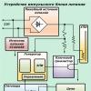
The most popular in everyday life are switching sources powered by a standard AC mains and a powerful low-voltage output. The block diagram of such a source is shown in the figure.
The CB network rectifier converts the alternating voltage of the supply network into direct voltage and smoothes out the ripples of the rectified voltage at the output. The high-frequency VChP converter converts rectified voltage into alternating or unipolar voltage, which has the form of rectangular pulses of the required amplitude.
Subsequently, this voltage, either directly or after rectification (VN), is supplied to a smoothing filter, to the output of which a load is connected. The VChP is controlled by a control system that receives a feedback signal from the load rectifier.
This device structure can be criticized due to the presence of several conversion stages, which reduces the efficiency of the source. However, with the correct choice of semiconductor elements and high-quality calculation and manufacture of winding units, the level of power losses in the circuit is low, which allows obtaining real efficiency values above 90%.
Schematic diagrams of switching power supplies
Solutions for structural blocks include not only the rationale for choosing circuit implementation options, but also practical recommendations for selecting basic elements.
To rectify single-phase mains voltage, use one of the three classic schemes shown in the figure:
- half-wave;
- zero (full-wave with a midpoint);
- half-wave bridge.

Each of them has advantages and disadvantages that determine the scope of application.
Half-wave circuit It is characterized by ease of implementation and a minimum number of semiconductor components. The main disadvantages of such a rectifier are a significant amount of output voltage ripple (in the rectified one there is only one half-wave of the mains voltage) and a low rectification coefficient.
Rectification factor Kv determined by the ratio of the average voltage at the rectifier output Udк effective value of phase network voltage Uph.
For a half-wave circuit Kv=0.45.
To smooth out the ripple at the output of such a rectifier, powerful filters are required.
Zero or full-wave circuit with midpoint, although it requires twice the number of rectifier diodes, however, this disadvantage is largely compensated by the lower level of ripple of the rectified voltage and an increase in the rectification coefficient to 0.9.
The main disadvantage of such a scheme for use in domestic conditions is the need to organize the midpoint of the mains voltage, which implies the presence of a mains transformer. Its dimensions and weight turn out to be incompatible with the idea of a small-sized homemade pulsed source.
Full-wave bridge circuit rectification has the same indicators in terms of ripple level and rectification coefficient as the zero circuit, but does not require a network connection. This also compensates for the main drawback - the doubled number of rectifier diodes, both in terms of efficiency and cost.
To smooth out rectified voltage ripples, the best solution is to use a capacitive filter. Its use allows you to raise the value of the rectified voltage to the amplitude value of the network (at Uph = 220V Ufm = 314V). The disadvantages of such a filter are considered to be large values of pulse currents of the rectifier elements, but this disadvantage is not critical.
The selection of rectifier diodes is carried out according to the average forward current Ia and the maximum reverse voltage U BM.
Taking the value of the output voltage ripple coefficient Kp = 10%, we obtain the average value of the rectified voltage Ud = 300V. Taking into account the load power and the efficiency of the RF converter (for calculation, 80% is taken, but in practice it will be higher, this will allow for some margin).
Ia is the average current of the rectifier diode, Рн is the load power, η is the efficiency of the RF converter.
The maximum reverse voltage of the rectifier element does not exceed the amplitude value of the mains voltage (314V), which allows the use of components with a value of U BM =400V with a significant margin. You can use both discrete diodes and ready-made rectifier bridges from various manufacturers.
To ensure a given (10%) ripple at the rectifier output, the capacitance of the filter capacitors is taken at the rate of 1 μF per 1 W of output power. Electrolytic capacitors with a maximum voltage of at least 350V are used. Filter capacities for various powers are shown in the table.

High-frequency converter: its functions and circuits
The high-frequency converter is a single-cycle or push-pull switch converter (inverter) with a pulse transformer. Variants of RF converter circuits are shown in the figure.

Single-ended circuit. Despite the minimum number of power elements and ease of implementation, it has several disadvantages.
- The transformer in the circuit operates in a private hysteresis loop, which requires an increase in its size and overall power;
- To ensure output power, it is necessary to obtain a significant amplitude of the pulse current flowing through the semiconductor switch.
The circuit has found its greatest application in low-power devices, where the influence of these disadvantages is not so significant.
 To change or install a new meter yourself, no special skills are required. Choosing the right one will ensure correct metering of current consumption and increase the security of your home electrical network.
In modern conditions of providing lighting both indoors and outdoors, motion sensors are increasingly used. This not only adds comfort and convenience to our homes, but also allows us to save significantly. You can find out practical tips on choosing an installation location and connection diagrams.
Push-pull circuit with the middle point of the transformer (push-pull). It got its second name from the English version (push-pull) of the job description. The circuit is free from the disadvantages of the single-cycle version, but has its own - a complicated design of the transformer (the production of identical sections of the primary winding is required) and increased requirements for the maximum voltage of the switches. Otherwise, the solution deserves attention and is widely used in switching power supplies, made by hand and not only.
Push-pull half-bridge circuit. The parameters of the circuit are similar to the circuit with a midpoint, but does not require a complex configuration of transformer windings. The inherent disadvantage of the circuit is the need to organize the middle point of the rectifier filter, which entails a fourfold increase in the number of capacitors.
Due to its ease of implementation, the circuit is most widely used in switching power supplies with power up to 3 kW. At high powers, the cost of filter capacitors becomes unacceptably high compared to semiconductor inverter switches, and a bridge circuit turns out to be the most profitable.
Push-pull bridge circuit. The parameters are similar to other push-pull circuits, but there is no need to create artificial “midpoints”. The price for this is double the number of power switches, which is beneficial from an economic and technical point of view for building powerful pulsed sources.
The selection of inverter switches is carried out according to the amplitude of the collector (drain) current I KMAX and the maximum collector-emitter voltage U KEMAKH. For the calculation, the load power and the transformation ratio of the pulse transformer are used.
However, first it is necessary to calculate the transformer itself. The pulse transformer is made on a core made of ferrite, permalloy or transformer iron twisted into a ring. For powers up to several kW, ferrite cores of ring or W-shaped type are quite suitable. The transformer is calculated based on the required power and conversion frequency. To eliminate the appearance of acoustic noise, it is advisable to move the conversion frequency outside the audio range (make it above 20 kHz).
It must be remembered that at frequencies close to 100 kHz, losses in ferrite magnetic cores increase significantly. The calculation of the transformer itself is not difficult and can easily be found in the literature. Some results for various source powers and magnetic circuits are given in the table below.
The calculation was made for a conversion frequency of 50 kHz. It is worth noting that when operating at high frequencies, the effect of current displacement to the surface of the conductor occurs, which leads to a decrease in the effective area of the winding. To prevent this kind of trouble and reduce losses in the conductors, it is necessary to make a winding of several conductors of a smaller cross-section. At a frequency of 50 kHz, the permissible diameter of the winding wire does not exceed 0.85 mm.
![]()
Knowing the load power and transformation ratio, you can calculate the current in the primary winding of the transformer and the maximum collector current of the power switch. The voltage on the transistor in the closed state is selected higher than the rectified voltage supplied to the input of the RF converter with some margin (U KEMAKH >=400V). Based on this data, keys are selected. Currently, the best option is to use IGBT or MOSFET power transistors.
For rectifier diodes on the secondary side, one rule must be followed - their maximum operating frequency must exceed the conversion frequency. Otherwise, the efficiency of the output rectifier and the converter as a whole will decrease significantly.
Video about making a simple pulse power supply device