What wire colors do they represent? Brown and blue wire - which one is positive, which one is negative
In order to facilitate the installation of electrical wiring, all cable and wire products have appropriate different color coding. As a rule, in houses or apartments, lighting is installed and sockets are connected using three wires. Each of them has its own purpose in the home electrical network. Therefore, the designation of the color of the ground wires has great importance. Due to this, installation time and subsequent repairs are significantly reduced. Thanks to color coding, any type of connection is not particularly difficult.
Ground wire
In most cases, the color yellow-green is used to indicate the ground wire. Sometimes you can find conductors with insulation only yellow color. Even less commonly used is light green. Typically, such wires are marked with PE symbols. However, if the ground wire is aligned with the neutral, it is designated as PEN. It is colored green-yellow and has a blue braid at the ends.
In the distribution panel, the grounding wire is connected to a special busbar, or to the housing and metal door. IN distribution box the connection is made with similar wires provided in lamps and sockets equipped with special grounding contacts. The ground wire does not need to be connected to the device protective shutdown(RCD), so these protective devices used where only two wires are used for electrical wiring.
Neutral conductor (neutral)
The color blue is traditionally used for the neutral conductor or neutral. The connection in the distribution panel is made through a special zero bus, designated by the symbol N. All blue wires are connected to this bus.

The bus itself is connected to the input via. In some cases, the connection can be made directly, without any additional automatic devices.
All neutral wires in the junction box of blue color are connected together and do not take part in commutation. The exception is the wire coming from the switch. Connection blue wires connection to sockets is carried out using a special zero contact, designated by the letter N. This marking is affixed to the back of each socket.
Phase wire color
The phase does not have any precise designation. Black, brown, red and other colors other than green, yellow and blue are quite common. In the distribution panel installed in the apartment, the connection of the phase wire coming from the consumer is made with a contact circuit breaker, located below. In other circuits, this conductor may be connected to a residual current device.

In switches, the phase is directly involved in switching. With its help, the contact is closed and opened - turned on and off. In this way, voltage is supplied to consumers, and, if necessary, this supply is stopped. In sockets, the phase conductor is connected to the contact marked L.
Wire Definition
Sometimes situations arise when it is necessary to determine the purpose of a particular wire if there is no marking on it. The simplest and most common way is. With its help, you can accurately determine which wire will be phase and which will be neutral. First of all, you need to turn off the power supply to the panel. After this, the ends of the two conductors are stripped and separated to the sides away from each other. Then you need to turn on the electricity supply and use the indicator to determine the purpose of each wire. If the light bulb lights up upon contact with the core, this is a phase. This means the other core will be neutral.

If there is a ground wire in the electrical wiring, it is recommended to use a multimeter. This device is equipped with two tentacles. First the measurement is established alternating current in the range of more than 220 volts at the corresponding mark. One tentacle is fixed at the end of the phase wire, and the second one determines grounding or zero. In case of contact with zero, the device display will display a voltage of 220 volts. When you touch the ground wire, the voltage will be noticeably lower.
Marking
There is not only the color of the wires phase, zero, ground, but also other types of markings, primarily alphabetic and digital designations. The first letter A indicates the wire material - aluminum. If this letter is missing, the core material will be copper.
Basic marking of wires in electrical engineering:
- AA - corresponds to a multi-core aluminum cable with an additional braid of the same material.
- AC - additional lead braid.
- B - the presence of protection from moisture and additional braiding made of two-layer steel.
- BN - non-flammable cable braid.
- G - absence of a protective shell.
- R - rubber shell.
- HP - rubber shell made of non-flammable material.
Anyone who has ever dealt with wires and electricity has noticed that conductors always have different insulation colors. This was done for a reason. The colors of the wires in electrics are designed to make it easier to recognize the phase, neutral wire and ground. They all have a certain color and are easily distinguished during operation. The color of the phase, neutral, and ground wires will be discussed further.
How phase wires are painted
When working with wiring, phase wires pose the greatest danger. Touching the phase, under certain circumstances, can become lethal, which is probably why they were chosen for bright colors. In general, the colors of electrical wires allow you to quickly determine which of a bunch of wires are the most dangerous and work with them very carefully.
Most often, phase conductors are red or black, but other colors are also found: brown, lilac, orange, pink, purple, white, gray. Phases can be painted in all these colors. It will be easier to deal with them if you exclude the neutral wire and ground.
In the diagrams, phase wires are designated by the Latin (English) letter L. If there are several phases, a numerical designation is added to the letter: L1, L2, L3 for a three-phase 380 V network. In another version, the first phase is designated by the letter A, the second by B, and the third by C .
Ground wire color
By modern standards, the ground conductor is yellow-green. It usually looks like yellow insulation with one or two longitudinal bright green stripes. But there are also transverse yellow-green stripes in color.

In some cases, the cable may only have yellow or bright green conductors. In this case, the “earth” has exactly this color. It is displayed in the same colors on diagrams - most often bright green, but it can also be yellow. Signed on circuit diagrams or equipment “ground” in Latin (English) letters P.E.. The contacts to which the “ground” wire must be connected are also marked.
Sometimes professionals call the grounding wire “neutral protective”, but do not be confused. This is an earthen one, and it is protective because it reduces the risk of electric shock.
What color is the neutral wire?
Zero or neutral is blue or light blue, sometimes blue with a white stripe. Other colors are not used in electrical engineering to indicate zero. It will be like this in any cable: three-core, five-core or with a large number of conductors.

“Zero” is usually drawn in blue on diagrams and signed with the Latin letter N. Experts call it a working zero, since, unlike grounding, it participates in the formation of the power supply circuit. When reading a diagram, it is often defined as "minus", while the phase is considered "plus".
How to check the correctness of marking and wiring
Wire colors in electrical engineering are designed to speed up the identification of conductors, but relying only on colors is dangerous - they could be connected incorrectly. Therefore, before starting work, you should make sure that you have correctly identified their affiliation.
Take a multimeter and/or an indicator screwdriver. It’s easy to work with a screwdriver: when you touch a phase, the LED built into the housing lights up. So it will be easy to identify phase conductors. If the cable is two-wire, there are no problems - the second conductor is zero. But if the wire is three-wire, you will need a multimeter or tester - with their help we will determine which of the remaining two is phase and which is zero.

We set the switch on the device so that the selected jackal is more than 220 V. Then we take two probes and hold them plastic handles, gently touch metal rod one probe to the found phase wire, the second to the supposed zero. The screen should display 220 V or the current voltage. In fact, it may be significantly lower - this is our reality.
If 220 V or a little more is displayed, this is zero, and the other wire is presumably “ground”. If the value is less, we continue checking. With one probe we again touch the phase, with the second - to the intended grounding. If the instrument readings are lower than during the first measurement, there is “ground” in front of you and it should be green. If the readings turn out to be higher, it means that somewhere there was a mistake with “zero” in front of you. In such a situation, there are two options: look for exactly where the wires were connected incorrectly (preferable) or simply move on, remembering or noting the existing position.
So, remember that when testing a phase-zero pair, the multimeter readings are always higher than when testing a phase-ground pair.
And, in conclusion, let me give you some advice: when laying wiring and connecting wires, always connect conductors of the same color, do not confuse them. This can lead to disastrous results - in best case scenario to equipment failure, but there may be injuries and fires.
Those who have dealt with electrical wires at least once in their lives could not help but notice that the cables always have different insulation colors. It was not invented for beauty and bright colors. Thanks to color scheme When wearing wire clothing, it is easier to recognize phases, grounding and neutral wires. All of them have their own coloring, which makes working with electrical wiring many times more convenient and safe. The most important thing for the master is to know which wire should be marked with which color.
Wire color coding
When working with electrical wiring, the greatest danger is represented by the wires to which the phase is connected. Contact with the phase can be fatal, so the brightest warning colors, for example red, were selected for these electrical wires.
In addition, if the wires are marked with different colors, then when repairing a particular part, you can quickly determine which of the wire bundles need to be checked first, and which of them are the most dangerous.
Most often for phase wires The following colors are used:
- Red;
- Black;
- Brown;
- Orange;
- Lilac,
- Pink;
- Violet;
- White;
- Gray.

It is these colors that phase wires can be painted. You can deal with them easier if you exclude the neutral wire and ground. For convenience, in the diagram the image of a phase wire is usually denoted by the Latin letter L. If there is not one phase, but several, a numerical designation should be added to the letter, which looks like this: L1, L2 and L3, for three-phase in 380 V networks. In some designs, the first phase (mass) may be designated by the letter A, the second by B, and the third by C.
What color is the ground wire?
According to modern standards, the grounding conductor should be yellow-green in color. In appearance it looks like yellow insulation, on which there are two longitudinal bright green stripes. But sometimes there is also a color of transverse green-yellow stripes.
Sometimes, the cable may only have bright green or yellow conductors. IN in this case“earth” will be indicated by this color. It will also be displayed in the corresponding colors on the diagrams. Most often, engineers draw bright green wires, but sometimes you can see yellow conductors. On diagrams or devices, “ground” is designated by the Latin (in English) letters PE. Accordingly, the contacts where the “ground” wire needs to be connected are also marked.
Sometimes experts call the grounding wire “neutral and protective,” but this should not be confused. If you see such a designation, then know that this is an earth wire, and it is called protective because it reduces the risk of electric shock.
The zero or neutral wire has next color markings:
- Blue;
- Blue;
- Blue with white stripe.
No colors are used in electrical engineering to mark the neutral wire. This is how you will find it in any, be it three-core, five-wire, or maybe with even more conductors. Blue and its shades are usually used to draw “zero” on various schemes. Professionals call it a working zero because (which cannot be said about grounding) it is involved in electrical wiring with power. Some, when reading the diagram, call it a minus, while everyone considers the phase “plus”.
How to check wire connections by color
Electrical wire colors are designed to make it easier to identify wires. However, relying only on the color is dangerous, because some newbie, or an irresponsible employee from the housing and communal services complex, could connect them incorrectly. In this regard, before starting work, it is necessary to ensure that they are correctly marked or connected.
In order to check the wires for polarity, take an indicator screwdriver or a multimeter. It is worth noting that it is much easier to work with a screwdriver: when you touch the phase, the LED built into the housing lights up.
If the cable is two-wire, then there are practically no problems - you have eliminated the phase, which means the second conductor that remains is zero. However, three-core wires are also common. Here you will need a tester or multimeter to determine. With their help, it is also not difficult to determine which wires are phase (positive) and which are neutral.
This is done as follows:
- The switch is set on the device in such a way as to select a jackal of more than 220 V.
- Then you need to take two probes in your hands, and holding them by the plastic handles, very carefully touch the rod of one of the probes to the found phase wire, and lean the second against the supposed zero.
- After this, the screen should display 220 V, or the voltage that actually exists in the network. Today it may be lower.

If the display shows a value of 220 V or something in this range, then the other wire is zero, and the remaining one is presumably ground. If the value that appears on the display is less, you should continue checking. We again touch the phase with one probe, and the supposed ground with the other. If the instrument readings are lower than in the case of the first measurement, then in front of you is “ground”. According to standards, it should be green or yellow. If suddenly the readings turn out to be higher, this means that you have made a mistake somewhere, and you have a “zero” wire in front of you. The way out of this situation is to either look for exactly where the wires were connected incorrectly, or leave everything as is, remembering that the wires are mixed up.
Wire designations in electrical diagrams: connection features
Starting any electric installation work on lines where the network has already been laid, you need to make sure that the wires are connected correctly. This is done using special testing devices.
It must be remembered that when checking the phase-zero connection, the readings of the indicator multimeter will always be higher than in the case of continuity of the phase-ground pair.
According to the standards, wires in electrical circuits are color coded. This fact allows the electrician to find zero, grounding and phase in a short period of time. If these wires are connected incorrectly to each other, a problem will occur. short circuit. Sometimes such an oversight leads to a person getting hit electric shock. Therefore, you cannot neglect the rules (PUE) of connection, and you need to know that the special color coding wires is designed to ensure safety when working with electrical wiring. In addition, this systematization significantly reduces the electrician’s work time, since he is able to quickly find the contacts he needs.
Features of working with electrical wires different color:
- If you need to install a new one or replace an old outlet, then it is not necessary to determine the phase. The plug doesn’t care at all which side you connect it to.
- In the case when you connect a switch from a chandelier, you need to know that it needs to be supplied with a specific phase, and only zero to the light bulbs.
- If the color of the contacts and phase and zero are exactly the same, then the value of the conductors is determined using an indicator screwdriver, where the handle is made of transparent plastic with a diode inside.
- Before identifying a conductor, the electrical circuit in a house or other room must be de-energized, and the wires at the ends must be cleaned and spread apart. If this is not done, they may accidentally come into contact and result in a short circuit.
The use of color marking in electrical engineering has made people's lives much easier. In addition, thanks to color coding, high level Safety has improved when working with live wires.
Designations and colors of wires in electrical engineering (video)
Rating 4.50 (1 Vote)
Electric current is especially dangerous for humans, and it is also invisible. When installing wiring, wires are used different colors for safe and fast work, letters and numbers indicate the wire cross-section. Color and symbol designations or, in other words, markings are prescribed in the standards; you should not violate them so as not to endanger your own and others’ lives.
Color coding of core insulation
Visually, the wires differ from each other not only in color and diameter, but also in the number and type of cores. Depending on this characteristic, single-core and multi-core electrical wires are distinguished. Their variety finds its application in alternating current circuits, both in industrial three-phase networks with a voltage of 380V, and in a home single-phase network of 220V. Power circuits direct current use the same standard of electrical wires.
Single-phase two-wire network 220V
This type of network includes an outdated type of wiring, where aluminum wires in a single white braid, popularly known as “noodles,” are used as cores. One core of the electrical wire is a phase conductor, the second core is a neutral conductor. A single-phase two-wire network is used for ordinary household needs: simple sockets and switches.
About how to properly arrange an in-house electrical network.
The problem when installing single-color wiring is that it is difficult to determine the phase and neutral wires. The presence of additional measuring equipment will help to cope with the task; you can use a multimeter or a special screwdriver with an indicator, a probe, a tester, or a “continuity tester”.
The design of a single-phase two-wire network is permitted by GOST for premises with a small load on the electrical network and low safety requirements. In such cases, two single-core wires or one two-core wire with wires of different colors are used.
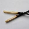
When using a solid wire, one core is brown, the other blue or cyan. According to generally accepted markings, the brown conductor is a phase, and the blue conductor is a neutral conductor; it is strictly not recommended to violate this order. In practice, there are phase wires in colors other than brown: black, gray, red, turquoise, white, pink, orange, but not blue.
The use of two independent single-core wires also requires marking. You can use a wire colored along the entire length, for example, blue for zero, red for phase. It is permissible to mark wires of the same color with electrical tape or heat-shrinkable tubing of different colors, placing the marking on both ends of each wire.
The use of a tube does not involve wrapping the ends, but putting it on the wire and exposing it to hot air in order to fix the heat shrink on the wire. For home use You can use any colors of marking materials that are accessible and understandable to the wiring installer.
Single-phase three-wire 220V network and markings used in it
Modern requirements for the installation of electrical wiring dictate the presence of a third wire - grounding. This is the difference and main advantage of a single-phase three-wire network.
Three electrical conductors perform the corresponding functions: phase, neutral and grounding, protection against injury from alternating current. The marking of the phase wire remains brown, the neutral wire remains blue or light blue, and the ground wire must be braided in a yellow-green color.

Household appliances that comply with European safety standards require connection to earthed sockets. Such sockets have a special contact to which a yellow-green wire is connected. It is strictly not recommended to use this color to mark phase and neutral wires in order to avoid possible unpleasant consequences.
Three-phase network 380V
A three-phase network, just like a single-phase one, can be with or without grounding. Depending on this, a three-phase four-wire electrical network with a voltage of 380V and a three-phase five-wire network are divided.
A four-wire network consists of three phase conductors and one neutral working conductor; there is no protective grounding conductor here. In a five-wire network, in addition to three phase conductors and one neutral, there is also a grounding conductor.

Similarly with two-phase marking of conductors, a blue or cyan conductor is used for the neutral conductor, yellow-green for the grounding conductor. Phase A is brown, phase B is black, phase C is marked gray. There may be exceptions to the rules for phase conductors; their color marking allows the use of other colors, but not blue and yellow-green, which already have their own function.
When distributing single-phase loads into groups or connecting three-phase loads, four-core and five-core wires are used.
DC network
A DC network differs from an AC network in that it contains two conductors: plus and minus. The core of the positive conductor is marked in red, and the core of the negative conductor is marked in blue.
The practice of color separation of wires is familiar to professionals and amateurs; it is actively used in electrical engineering, but still you should not blindly trust the markings. Backing up with a measuring device is a thoughtful and balanced move when installing electrical networks; you should not neglect it.

If you are an electrician, we would appreciate your feedback on this article. Please write your comment below.
Currently, the industry produces electrical wires different sections with alphanumeric and color markings along the entire length of the wire. Main function any type of marking - visual recognition of each individual wire strand according to its intended purpose, as well as facilitating (accelerating) the installation and operation of wires.
In addition, the separation of cores by color in a power electrical circuit is also one of the modern safety requirements regulated by GOST.
Electric wire widely used in production and in everyday life both in AC power circuits (single-phase 220V network or three-phase 380V network) and in DC circuits. Electrical wire can be single-core or stranded. The wire cores can be single-wire or multi-wire.
Single-phase two-wire network 220V
A two-wire electrical network is an electrical network with two electrical conductors. One conductor is phase, the second is neutral. Two-wire electrical systems are still found in older homes today in the form of conventional electrical wiring. Old electrical wiring is a two-wire aluminum wire(“noodles”) with white insulation.
A two-core wire is used to connect switches, ordinary sockets, and lamps.
Because Since both wires of such a wire have the same color, it is quite problematic to visually distinguish phase from zero. Therefore, in order to determine where the phase is and where the zero is, use an indicator screwdriver, a probe, a “continuity tester,” a tester, a multimeter or another electrical measuring device.
Today, in order to distinguish a phase from zero during operation, during installation either a two-core wire with cores of different colors or two single-core wires are used.
As a two-core wire, a flexible wire with a brown and blue (light blue, light blue) core is often used. It is strongly recommended to use a brown conductor as a phase conductor, and a blue conductor as a neutral conductor.
Often there are two-core wires with different colors of cores. For example, in such wires the phase wire may not be brown, but red, black, gray or another color.
If two separate single-core wires are used, there are two marking options. The first is the use of wires of different colors. For example, you can use a red wire as a phase, and a blue wire as a zero.
If wires of the same color are used, then the phase and neutral wires can be marked either using colored electrical tape, or by using colored heat-shrink tube. When using colored electrical tape, red electrical tape is wound on the phase wire at the beginning and end, and blue electrical tape is wound on the neutral wire.
When using heat shrink, marking single-color wires is almost the same as marking with electrical tape. Red heat shrink is put on the phase wire, and blue heat shrink is put on the neutral wire.
At home, you can mark wire cores with other colors.
Color marking in a single-phase three-wire 220V network
A three-wire electrical network is a network with three electrical conductors. Currently, a three-wire network is becoming more and more common, especially for new wiring.

As in a two-wire network, one conductor is phase, the second is neutral, but the third conductor is a protective ground wire that serves to protect against electric shock. A three-wire network uses a three-core wire, usually with a brown, blue and yellow-green core.
The brown conductor is a phase, the blue conductor is the neutral conductor, the yellow-green conductor is the protective grounding conductor. To avoid confusion, it is not recommended to use a yellow-green colored conductor as a phase or neutral conductor.
A three-core wire with colored cores is used to connect modern sockets European standard, having in addition to the phase and neutral contacts also a contact for connecting the grounding conductor. Three-core wires are also used to connect lamps.
Color codes for wires in a three-phase 380V network

A three-phase electrical network can be four-wire or five-wire, i.e. with four or five wire cores. The only difference is the presence or absence protective conductor grounding. Those. a four-wire network consists of three phase conductors, a neutral working conductor and the absence of a protective grounding conductor. A five-wire network consists of three phase conductors, a neutral working conductor and the presence of a grounding conductor.
In both four-wire and five-wire networks, a blue conductor is used for the neutral working conductor, and a yellow-green conductor is used for the grounding conductor. Concerning three phases A, B and C, then most often brown, black and gray cores are used for them, respectively. But there are also other colors of wire cores.
A four-core and five-core wire is used to connect a three-phase load or to divide a single-phase load into groups.
DC network
A DC electrical network typically uses two conductors. The first conductor is positive, and the second conductor is negative. A red wire is used as a positive conductor, and a blue wire is used as a negative conductor.
Based on the results of all of the above, it is worth noting the following: despite certain standard requirements for color marking of wires, without preliminary checking it is not recommended to rely 100% on the color of a particular wire core.