Wiring of wood-burning boilers. We are drawing up a wiring diagram for a solid fuel heating boiler. Application of additional boilers
Everyone who uses it to heat their homes solid fuel boilers, they know that regardless of the model, it is impossible to organize a uniform supply and combustion of fuel in this system. When it burns out, the temperature of the coolant and air in the room drops quite quickly. The owner is forced to regularly supply fuel, and this is not always possible. Decide this problem Connecting a buffer tank to a solid fuel boiler will help. All the advantages and disadvantages of this heating system operation scheme will be discussed in this publication.
Save fuel and extend the life of your boiler!
Boilers only perform optimally if they can generate heat at their rated output. Since boilers, especially for solid fuel, provide much more power than the house needs to heat, on the one hand, excess energy must be released into one, but, on the other hand, the return flow temperature must be high enough to prevent the boiler from cooling.
If the water temperature in the boiler is too low, condensation occurs to form water vapor and tar and soot in the combustion chamber. This leads to weaker combustion and early boiler failure due to corrosion. Supports buffer storage with low flow and high, even high temperature. To do this, please consider our recommended connection option, in which the boiler and house are connected via a line in a buffer. Increases the temperature when the boiler returns. This prevents corrosion of the boiler and increases the service life of the boiler. Completely fills the buffer memory with the thermal valve, completely closing the bypass at the end of the heating process. Lever ball valves make it easier Maintenance without draining the system. Lever ball valves have a medium high throughput, providing a high flow rate at the end of the heating process, as well as during autonomous circulation. Ball Valves with padded boxes for long, trouble-free operation. With locking gravity brake. Three thermometers allow you to fully control the charging process. Easy assembly thanks to very small sizes installation and light weight.
- Quickly achieve what you want operating temperature boiler
- This ensures optimal thermal coverage in the buffer storage.
Design and principle of operation
IN simplest design buffer tank (heat accumulator, storage tank) is a thermally insulated metal tank with four pipes: two for the boiler circuit and two for the circuit heating system.
At the top of the device there is a blast valve, which, if necessary, releases excess pressure. At the bottom of this device a drain valve is installed, thanks to which the coolant can be drained. Some heat generator models provide for the presence of an electric heating element and (or) a coil for heating the coolant from other heat sources. Quite often, in the upper part of the structure there is a heat exchanger, thanks to which water is heated for the domestic hot water supply.
Other buffers are usually connected only in series. If necessary, a pump must be provided for overloading. In this option, all buffers are connected in parallel. Disadvantage: All 3 magazines have a high to low temperature transition caused by internal radiation and conduction. in a steel shell results in greater balance between layers. To enlarge the connection diagram, click on the picture.
Application of buffer tank
These are recommendations. Depending on your personal situation, other sections may be helpful or necessary. If you are planning to install, please consider that copper cables have the highest price, but have no advantages compared to pipes with a lower price for the heating function. Our recommendation is C steel or similar or multi-layer composite pipe. Specially corrugated pipe and composite pipe significantly speed up installation, resulting in further cost savings.
The operating principle of this device is as follows: the tank is filled with coolant. When starting the boiler circulation pump The boiler circuit supplies cooled coolant from the lower part of the heat accumulator, which, after heating, enters the upper part of the buffer tank. Hot coolant is lighter than cold coolant, so it is always in the upper part of the tank. While the solid fuel boiler is operating in a small circle (only through the buffer tank), the cold coolant is gradually replaced by hot one.
For all these systems you can refer to all materials. We will be happy to inform you of your choice. Follow the rules when installing each type of ladder. which are listed in! You can order all spare parts! How to choose a boiler central heating for your needs?
First, determine the boiler power that will be needed to heat your room. If so, you can read the indicative boiler power in the following table. If you have, for example, the intention to warm two levels of a house measuring 7 by 10 meters, then the area you want to warm.
After all the coolant has warmed up, the circulation pump of the heating circuit is turned on, and the heated coolant from the top of the tank begins to flow into the heating system. The cooled return flows into the lower part of the storage tank, and from there into the boiler unit. 
Piping diagrams in systems with hydraulic separator
Therefore, you should choose a boiler with a power of about 16 kW. If the height of the rooms you are going to heat is different. The main fuel of many boilers is usually coal or coke. When replacing low-calorie fuel with lower calorific value, such as wood, the boiler must be higher. Therefore, always pay attention to which fuel receives the rated power, e.g. wood boilers the power is already given for wood. The above table applies to older houses.
Due to the difference in density, the hot and cold coolant in the buffer tank practically does not mix.
The main advantages of this heating scheme are that when the boiler stops, this system will continue to supply the radiators with hot coolant for some time. Correct selection of buffer capacity for solid fuel boiler allows you to significantly increase the time between boiler fires, reduce fuel consumption and save money. In addition, the use of this device will smooth out temperature fluctuations in the boiler and heating circuit.
When your heating system is modern with little water in the pipes and the building is well insulated, you can choose a boiler one step down. The above recommendations for boiler release already include heating hot water. To provide good combustion boiler fuel without a feeder it is equipped with automatic aeration.
Engine internal combustion- mechanically raises the lower inlet door according to the required temperature. Fan - blows air into the combustion chamber, the fan is used in conjunction with the controller. This equipment is sometimes included, and sometimes it is optional.
The disadvantage of heating with a heat accumulator is that a fairly long period passes between starting the boiler and warming up the radiators. Depending on the room temperature and tank capacity, this time can be 2-4 hours.
Let's digress a little, because we want to inform you that we have compiled a rating of solid fuel boilers by model. You can learn more from the following materials:
If you value your comfort and can afford financial position, it is recommended to purchase an environmentally friendly boiler with an automatic fuel feeder. Characteristic feature These boilers have a hearth that burns part of the fuel necessary to achieve the desired water temperature. The air flow is also automatic, so the exhaust gases emitted during boiler operation are clean. The kit includes a controller, fan and fuel feeder with motor. Boiler operation is reduced to periodic filling fuel tank fuel.
Strapping scheme
The heat generator cannot function properly without piping.
The heat generator is installed parallel to the boiler unit and the heating circuit in the gap between them. Connecting a solid fuel boiler with buffer capacity includes two circulation pumps for the boiler and heating circuit, a three-way valve (for the boiler circuit) and a balancing valve (for heating circuit), expansion tank, blast and drain valve, pressure gauge. 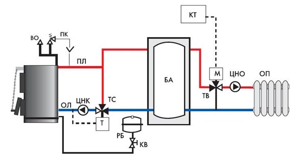
The container can be located on the left or right side of the boiler. In a boiler we always look at the front of the boiler, which is the driver's side. Boilers with automatic feeding fuels are also used to heat hot water. Feeder boilers are the best source of heat in your home.
In Poland, installation of boilers for solid fuels is most often carried out in open systems. In the most high point In this installation, as a safety device, we install an open expansion vessel. Below is an example of an open vessel. If the legislation of your country and the boiler operating instructions allow installation in closed systems ah, this option is good choice. However, it is necessary to properly protect the boiler and installation from excessive pressure and boiling water.
- Three-way thermostatic valve on the boiler circuit it creates movement of the coolant along a small circuit until its temperature reaches the set value. After heating the coolant, the valve blocks the movement of the hot coolant and opens the way for the return flow from the heat accumulator. Installed between supply and return on the boiler circuit.
- The balancing valve will allow you to regulate the return temperature by mixing hot coolant to it in order to prevent the formation of condensate on the boiler heat exchanger. The balancing valve on the heating circuit protects radiators from overheating by reducing the supply of coolant (bypassing the heating system) to the return.
- The expansion tank compensates for the thermal expansion of the coolant.
- The blast and drain valve is a safety group that operates in the event of excessive coolant pressure. A pressure gauge is an element of a safety group that shows the pressure in the system.
- A return coarse filter is installed to protect the three-way valve
- Don’t forget about installing a cooling valve on the supply pipe, which, when the coolant temperature exceeds 90°C, mixes tap water into it.
The piping scheme for a solid fuel boiler with a buffer tank, as a rule, includes circulation pumps that move the coolant along the circuits.
When it is allowed to install boilers in closed systems, this is a good option. Safety should be threefold. IN closed loop there is no open dish, but the so-called. diaphragm vessel. Also install safety valve. 1.5 bar for boilers up to 65 kW.
Installation is safe with two safety valves. We recommend setting the safety group on the power supply and going back to the safety valve itself. The installation must also have protection against boiler overheating. One of the following two solutions applies.
Tip: For proper operation system, it is necessary that the performance of the heating circuit pump is slightly higher than that of the boiler pump. For a house with an area of up to 300 m 2, the required boiler pump parameters are 25/40; (25 mm connection diameter, 40 – head 4 m); pump parameters for the heating circuit 25/60 (25 mm connection diameter, 40 - pressure 6 m). Fine adjustment is made after the initial start-up of the system.
Some boilers have a cooling coil already built into the boiler. For example, in other steel boilers and in all cast iron boilers the coil must be connected to the system as separate element. This solution is usually used for large boilers, for example with an output power of more than 50 kW, for which an external cooling coil is not sufficient.
Each installation must be secured with 1.5 bar and 2 bar safety valves. It's time to connect the boiler to the chimney, which is usually used in the form of a straight pipe about 35 cm long or in the form of an elbow. For example, a direct connection connection is shown in the following figure.
A rough calculation of the buffer capacity of a solid fuel boiler is made according to the algorithm: for 1 kW of boiler installation power, a tank with a volume of 20 to 40 liters is required. It is these indicators that allow the system to work most efficiently. You can calculate the volume of the tank more accurately (up to a liter), but then you will have to take into account: the heated area, calculate the heat loss of the home under various weather conditions, find out the amount of coolant that the system needs per hour of operation at the lowest temperature in your region. The time between fires of the boiler installation must be multiplied by the calculated value. The result obtained will be the volume of the heat accumulator required for your system.
An installation with a pump has less inertia, and the heat also reaches the most distant radiators. Vertical height is the distance from the boiler to the highest radiator. To prevent the pump from running all the time, you should buy a pump that will turn off the boiler when the boiler is finished. If the boiler has a controller that controls the operation of the boiler fan, you can usually connect the same pump to the same controller and no additional pump controller is needed. It is also important that the boiler also heats hot water.
A heat exchanger is required. Such a heater must have water jacket or reel. If we plan to install solar system in the future, then we can buy a large container with two coils. To extend the life of the boiler and save fuel, it is recommended to use a four-way mixing valve. The following documents describe its operating principle.
How to make your own battery tank
 Due to the fact that these installations are quite expensive, many of our compatriots ask: “How to make a buffer tank for a solid fuel boiler with your own hands?” In principle, nothing is impossible for a person with “straight hands”, knowledge of the basics of heating engineering, and possessing necessary material, a tool, the skills to use it and an indecent amount of free time.
Using a three way valve
It is easiest to select the indicative power of the boiler on the basis of an indicator related to the volume of heated premises. The value of this indicator depends on the degree of thermal insulation of the building. Let's consider the boiler power for a building without thermal insulation. Let's look at the boiler output for a new house with very good thermal insulation.
Therefore, the boiler must have power. The above sentences are indicative. It is the boiler power that always represents the design of a house or installation. If in doubt, please contact us. To provide correct use The instructions for use, identification plate information and technical data must be observed. Installation of the boiler in residential premises and halls is not allowed. The boiler can only be installed and operated in ventilated rooms. The boiler is only allowed with appropriate automation.
If you have all of the above, then you need to:
- weld a sealed container of the required volume; Must be used stainless steel, thickness of at least 1.5 mm.
- make an insertion of fittings with a diameter of 1 inch and with the necessary threads for connection with boiler equipment and the heating system;
- embed a blast valve into the upper part of the device, and a drain valve into the bottom;
- insulate the tank basalt fiber, 100 mm thick.
- weld a casing made of thin galvanized steel, based on the external dimensions of the insulated tank.
- Place the device on the legs.
- Paint the device.
Based on experience, you won’t be able to save money by making your own heat accumulator for a solid fuel boiler. For almost the same money, a new battery tank will be safer, more durable and functional.
The piping of a solid fuel heating boiler must take into account all the features of this type of thermal energy generators, as well as the complexity and composition of the heating system itself: the number of circuits, the circulation pattern, the method of wiring and regulating the supply of coolant. In addition, the piping scheme for a solid fuel heating boiler must be chosen in such a way as to ensure not only the greatest efficiency, but also maximum safety of its operation. In this article we will look at several schemes of varying complexity that can be used, depending on the type and complexity of the heating system.
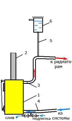
Fig. 1 Boiler piping diagram in an open system with natural circulation
The simplest is the wiring diagram for a solid fuel boiler for a single-circuit heating system with natural (gravitational) coolant circulation. As a rule, such systems use metal (most often steel) pipes with relatively large diameter, corresponding to the diameter of the boiler outlet and inlet pipes. It is best if their diameter is the same. This will allow, along with other factors, to reduce hydraulic resistance and create Better conditions for natural circulation. Such schemes are characterized by maximum simplicity and in the boiler piping it is necessary to try to avoid unnecessary elements that, to one degree or another, impede the natural movement of the coolant. Therefore, it is necessary to use shut-off or control valves to a minimum and only in places where it is impossible to do without them. Also, the presence of various filters in the circuit of such a system is undesirable. Most often, such systems are open. The expansion tank in them performs the function of creating excess pressure and removing air, therefore it is installed at the highest point, at the maximum possible height (under the ceiling or in the attic).
In Fig. 1: 1 - boiler; 2 — chimney; 3 - supply pipe (diameter 40-50 mm); 4 — “return” (diameter 40-50 mm); 5 - pipe (1/2); 6 - open type expansion tank.
In systems with combined circulation

Fig.2 Strapping diagram for open system with combined circulation
The scheme for a system with combined (combined) circulation is more complex, since it already provides for the presence in it of a special circulation pump, as well as the necessary elements of its piping (bypass, shut-off valves, filter mechanical cleaning, air valve). A bypass with a circulation pump can be installed both on the supply pipe and on the return pipe, depending on the availability of space for installation and the convenience of further maintenance.
The air valve is included in the bypass if it is installed on a horizontal section of the pipe and the design of the pump itself does not provide for the possibility of bleeding air.
In the event of a lack of electricity, the tap on the straight bypass pipe opens and the system operates with natural circulation. Instead of a tap, a valve is sometimes installed in this place, which opens automatically in the absence of electricity.
In Fig. 2: 1 - boiler; 2 - chimney; 3 - supply pipe; 4 — “return”; 5 — pipe 1/2″; 6 — expansion tank; 7 — shut-off valves; 8 - circulation pump; 9 - filter; 10, 11 - possible locations of the bypass on the “return” or supply line.
If the heating system is closed, then instead of the usual open expansion tank a sealed membrane is installed. This makes it possible to ensure the specified overpressure(usually it is about 1.5 bar (0.15 MPa). In addition, such a circuit must necessarily include a safety unit (safety valve, pressure gauge, air valve).
IN Lately, piping a solid fuel boiler with polypropylene is increasingly being used, that is, polypropylene pipes and fittings. This material has become quite popular because it is not susceptible to corrosion, is easy to install and has a relatively low cost.
In this case, it is necessary to remember such features of solid fuel heat generators as great inertia and the difficulty of quickly regulating the combustion temperature of the fuel, and therefore the coolant. Therefore, when piping such a boiler with polypropylene, it must be remembered that the supply pipe coming out of it must be metal at a distance of at least 1.5 m or until the first branch. The “return” can be completely plastic, since the liquid temperature in it rarely exceeds 70-80 ° C. But its internal diameter must correspond to the internal diameter of the metal supply pipe.
Piping diagrams in systems with hydraulic separator
In more complex systems that include several circuits (branches), piping schemes for solid fuel boilers with a hydraulic separator are often used, in the form of a cylindrical container, into the upper part of which heated coolant is supplied, and into the lower part cooled liquid from the system is supplied. From the upper part of the hydraulic separator, water is supplied to the comb (collector) and distributed between the circuits, and from the lower part to the boiler inlet pipe. Such schemes are usually used for closed systems with forced or combined circulation. Below are two possible options.
Option 1
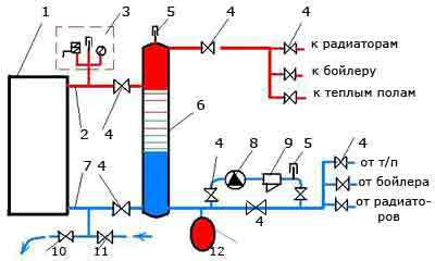
Fig.3 Piping diagram of a boiler with a hydraulic separator (option 1)
In Fig. 3: 1 - boiler; 2 - supply pipe; 3 — safety block; 4 - tap; 5 - air valve; 6 - hydraulic separator; 7 - return pipe; 8 - circulation pump; 9 - filter; 10,11 - taps for draining and supplying water; 12 - membrane tank.
Option 2
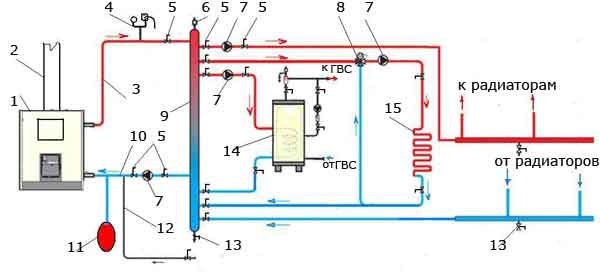
Fig.4 Piping diagram with hydraulic separator (option 2)
In Fig. 4: 1 - boiler; 2 - chimney; 3 - heated water; 4 — safety block; 5 - tap; 6 — air valve; 7 - circulation pump; 8 - three-way thermal valve; 9 - hydraulic separator; 10 — “return”; 11 - membrane tank; 12 - feed cold water into the system; 13 - drain valve; 14 - boiler; 15 - warm floor.
Circuit with heat accumulator
Sometimes a so-called buffer tank or heat accumulator is included in a water heating system. This allows you to accumulate thermal energy during operation of a solid fuel boiler and use it to heat the room in the intervals between the firebox. The piping diagram of a solid fuel boiler with a heat accumulator usually includes shut-off and control valves, pump groups with a control unit that ensures turning on or off a particular circuit and effective work the entire system.

Fig. 5 Boiler piping diagram in a system with a heat accumulator
In Fig. 5: 1 - boiler; 2 — safety block; 3 - electrical panel; 4 — buffer tank (heat accumulator); 5 - circulation pump; 6 - three-way thermal valve; 7 — control unit; 8 - taps; 9 - membrane tank; 10,11 - pumping groups.