The vertical plane has. Spirit level - keep the level during the repair! Horizontal assortment of goods seems more diverse
The spirit level, also called bubble level, is very often used on a construction site, as it allows you to quickly determine the deviation even by a small degree from the horizontal or vertical plane. Sometimes these errors can be critical for the result, so this tool is indispensable at the construction site.
Spirit level level - instrument device
As a rule, such a level looks like a rectangular bar, in which one or two (sometimes more) flasks with liquid are built in, you can also see a small air bubble in them, which is an indicator. When this ball occupies a place between two marks on the flask, then the surface under study is vertical or horizontal. If it stands for some kind of risk, then you can estimate the approximate degree of deviation.
Each flask (they are also called a peephole) is filled with a low-viscosity liquid so that the bubble can move easily, and an important requirement is the non-freezing of such a filler in the cold. Therefore, the main material for cones is alcohol, it is tinted a little more to make it easier to observe the measurement. The marks on which readings are taken are also applied to the flask, sometimes there are not two, but more, for increased accuracy.
The household bubble level rarely has more than two measuring flasks: one for examining the horizontal plane (180 degrees), and the second perpendicular to it for measuring the vertical (90 degrees). You can meet the third flask, which is adjusted to 45 degrees and fixed. Professionals can see a more bizarre instrument, where there are much more flasks, they duplicate the main ones to reduce the error, or measure other angles (for example, 60 degrees). Moreover, an instrument of any level is available for understanding to every master; there are never any difficulties with how to use a spirit level.
There is an electronic spirit level, which has a convenient display that shows the measurement results. This is determined not “by eye”, but with the help of acoustic effects, which makes the numbers more accurate, and the error is significantly reduced.
In addition to the main structural elements, useful additions can be found on the body, often helping out the builder during work. For example, a ruler located at some end of the level, or a milling surface, so that when installing the tool it is more stable and it would be easier to hold it (for example, when measuring vertically). You can also find on one side a notch-bend for sloping surfaces, such as pipes, to make it convenient to measure and their location in space.
Bubble level settings
Some bubble levels are adjustable. These are two inconspicuous screws on either side of the flask. Springs are hidden in the body under them, which set the flask to the required level, which you check with your own hands. As practice shows, a rare tool is really set up correctly, and many of these "unsuccessful" options do not have the ability to adjust, and those who know how to check the quality often part with a newly purchased tool. Moreover, even a properly adjusted level can go astray if it is dropped, from changes in temperature and humidity, or even from time to time.
To check the correct location of the flask in the body, put the level on any horizontal surface, if the bubble is in the correct position, turn the tool 180 degrees so that the ends just swap places, and put it again on the same surface. Evaluate the location of the bubble again, and if it has not changed, then everything is set up correctly. And it's not scary if the bubble is not strictly in the center, the main thing is that it does not fall out of the lines, and most importantly, that in these two positions it should be in the same error. If, for example, it is not strictly in the center, but slightly shifted to some kind of risk, then after the turn it should also be shifted in the same direction to the same extent.
In cases where such a check showed a different result, tighten the screw on the problem side and again conduct such a survey. For a vertical flask, the measurements are similar, the only difference is that you need to turn the tool a little differently, apply it to the surface first with one side, and then with the one that looked at you when measuring. That is, rotate the level around its axis relative to the floor. And the results are analyzed in the same way.
How to choose a spirit level?
Since the choice of levels is extremely large, having entered the store, we begin to gradually discard one selection criterion.
How to choose a spirit level - step by step diagram
Step 1: Length
First, let's select the length that our tool should be, it should be enough to measure in one step the plane of your building object. For example, when installing a window with a width of 1 m, the level should be just about this length. For small jobs fit the size of the palm. In the case of ceilings and walls, rather long tools are needed, 2 meters or more. But in the case of such a purchase, be prepared to diligently protect it from falling, because for such a "shaft" it will be the first and last. There are even giants (about 4 m), but they are telescopic, i.e. are put forward during operation, and are stored in a somewhat reduced form, but we suspect the presence of large errors in its operation, since it is desirable to have a solid body.
Step 2: Case material and profile
Next, choose a material, it must be rigid, preferably from some kind of alloy, because plastic is extremely short-lived. Today, there are many alloys that are light in weight, but strong enough to make the body of the level, and rigidity is achieved by a certain structure of the tool profile. Most often there are T and H profiles, the second option is more reliable.
Step 3: Flasks
We have already talked about their device, it remains to present practical requirements for them. Firstly, find the indication of the measurement error from the manufacturer, and secondly, check the adjustment directly in the store and do not forget to do this at the beginning of each construction cycle. Pay attention to how sensitive the flask is, for this, put something thin under the level, the bubble should change its position, and so that it is noticeable to the eye. For professional models, you can even use a sheet of paper for this purpose, since their sensitivity should be quite high. This parameter depends on the curvature of the bulb, and hence on its material and shape. It would also be nice if the risks were applied to the flask from the inside, as they are quickly erased from the outside, and the device becomes useless.
Step 4: Case Assembly
In the end, you should turn the future purchase in your hands, see how well the case is assembled, whether it has any distortions, backlashes. Especially important is the place of fastening of the plugs along the edges and fixation of the flasks. All this should be fixed in an understandable way, and quite securely, so that even a hint of a shift cannot be observed with a slight pressure. The flask mount should be accessible for adjustment, and it is better to choose the plugs on the body from rubber, so damage to it is less likely if careless.
The participants in such rendezvous cases are aircraft that perform level flight at adjacent oncoming flight levels. Due to technical errors in maintaining altitude, the trajectory of each of the aircraft can be shifted vertically towards the other. This can also be caused by rounding errors in the transmission of altitude data, especially at 100-foot sampling intervals. As a result, the altitude separation estimate between these aircraft used by the TCAS II systems logic program is less than 1000 ft. When the altitude difference reaches 850 ft, a (=>) TA warning will be issued, and at a difference of 700 ft, an RA advisory will be issued. Such a variant of the aircraft rendezvous is shown in Fig. 1.23.
Pilots in this case should not request air traffic information from the air traffic controller, nor should they maneuver based on TA alone. At large offsets, TCAS II systems may issue limiting recommendations. Such an event of convergence will not affect the work of air traffic controllers in any way.
Flight trajectory fluctuations.
The participants in such rendezvous cases are aircraft that also perform level flight at adjacent oncoming flight levels.
When maintaining a given altitude, the flight path of the aircraft may fluctuate vertically. As a consequence, the altitude separation estimate between these aircraft may be less than 1000 ft, and in some rare cases a TA warning may be issued, as shown in Fig. 1.24.
 |
This option is a rare event, since a TA is possible when one aircraft is equipped with an ATCRBS transponder with a 100 ft altitude data sampling interval, or when the amplitude of the simultaneous oppositely directed oscillations of the trajectories of both aircraft is 51 feet.
Pilots, in this case, should not request air traffic information from the air traffic controller, and also should not maneuver on the basis of only TA. Such an event of convergence will not affect the work of air traffic controllers in any way. There is no specific procedure to be followed in such a case.
Turbulence.
There may be cases of rendezvous with an aircraft that has entered the zone of atmospheric turbulence or wake turbulence. At the same time, sharp deviations are observed in the direction of another aircraft located at an adjacent oncoming echelon, with a high instantaneous vertical speed and significant acceleration. The logic programs of the TCAS II systems of both aircraft perceive these movements as a deliberate approach and can issue TA recommendations or even “sudden” RAs (Fig. 1.25).
 |
When issuing TA alerts, pilots should not request air traffic information from an air traffic controller, nor should they maneuver based on TA alone. The primary purpose of a TA is to alert the flight crew to the possibility of an RA. When issuing a "sudden" RA, one should follow its recommendations, which are more likely for this case - limiting. Performing a sideshift maneuver due to a "sudden" RA is not an approved procedure. The air traffic controller should not attempt to change the flight path of the aircraft, but provide traffic advisories when necessary.
Exit to level flight at an adjacent flight level.
In such cases of approach, one aircraft flies horizontally at its cleared flight level, and the other aircraft occupies its cleared adjacent flight level by climbing or descending at an excessively high vertical speed, for example, 12 m/s (Fig. 1.26).
The results of the TCAS II logic calculations will predict that at this vertical speed both aircraft will soon be at the same height. In such cases, the TCAS II systems of both aircraft issue TA warnings first, and then RA recommendations are possible. In the process of approaching an aircraft, the altitude check is based on the calculation of the flight time to the point of closest approach, i.e. until the altitude of another aircraft is reached. In this example, 48 s for the issuance of a TA, and for the recommendation of an RA - 35 s for a maneuvering aircraft and 25 s for an aircraft performing level flight. Thus, the crew of a maneuvering aircraft will receive an RA earlier - at a height separation of 1400 ft. To avoid issuing TA warnings and RA advisories, pilots should maintain a vertical speed of less than 7.6 m/s in such cases of close approach at the final stage when approaching the cleared flight level.
Modern technologies have already made hand tools more efficient - the chisel has replaced the hammer drill, the electric drill has replaced the mechanics, electronic computing modules have appeared in theodolites and levels, and ordinary construction twine, squares and plumb lines are gradually giving way to laser devices (hereinafter referred to as LP).
On laser devices for building and finishing.
Laser plummet and level, laser level and rotary laser, laser marker and builder, laser tape measure and range finder - all these names are related to a modern and efficient tool used in the breakdown of land, building construction, interior decoration, installation of communications. These devices allow you to build a basic horizontal, vertical or inclined plane, directly on the wall, floor, ceiling and control them visually or with the help of special receivers and leveling rods.
Tasks of the LP
A completely flat laser beam successfully replaces a plumb line, spirit level, metal square, building string or cord, and even a tape measure, especially at distances up to 200 meters. How much easier and more accurate it is to build a wall, a column, install a door frame or a window, when you can clearly control the deviation from the vertical with the help of a red line of a laser beam passing through them, accurately tied to the vertical, and with a laser tape measure that allows you to measure distances to inaccessible areas . LP allow you to quickly and conveniently check the horizontal and general level of the foundation, design the slope of a water pipe or drain, plan the slopes of the land, install the fence and siding, control the laying of bricks and tiles, mark beacons for mounting ceilings and pouring the floor, mount telescopic gates and roof, to help everyone, without exception, to do their work effectively.

|

|

|
How LPs work
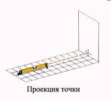
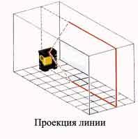
Many people are already familiar with the laser pointer, which children often use to point the red dot of the laser at objects. It is this principle that laser devices use to project a horizontal, vertical, inclined plane or point directly onto the work surface. Pictures show this best:
|

|
|

|
Inside the device, a red laser LED is usually installed, with a power of about one mW and a wavelength of 633 - 670 nm, belonging to the second class of lasers, assuming no additional eye protection. The LED is located in a fairly durable case and, using an electronic circuit, interacts with the control panel and receives power. In order to focus the LED radiation to a point or to get a line, optical elements of various shapes (cylindrical, conical, etc.) are used.
The laser emitter can be rigidly fixed inside the instrument or be free-hanging for self-alignment. In self-leveling lasers, the "pendulum principle" is used - the emitter is suspended inside the device and, when installed on the surface, aligns itself with respect to ground level and produces an accurate horizontal, vertical or oblique beam projection. To reduce the balancing time of the pendulum with the emitter, magnetic cushions are often used, formed by magnets built into the bottom of the device. In more complex LPs, a system similar to a gyroscope is used, which electronically controls the emitter servos built into the device, allowing it to balance and even set the required slope.
Instruments with a self-balancing transducer are often equipped with an automatic alarm for critical case tilt (typically more than 5% of the horizontal), which helps to avoid erroneous projections and measurements. Simply put the device on a relatively flat surface and turn it on - the device will automatically balance the emitter relative to the horizon within a few seconds and ... Let's get to work!
Laser level
Inside the laser level (hereinafter referred to as LU), the emitter is fixed relative to the alcohol bubble and can project a point to a remote distance at the same level and in the same vertical plane, simultaneously acting as a level and a stretched string between the level and the projection point. The Stabila 70LJ level with one emitter can be purchased at a price of 2250 rubles.
One of the most popular LU models, Stabila 70LJ P+L, is manufactured by the German company Stabila and has two transverse emitters, which allows it to be used for a wider range of applications (Fig. 1). Another novelty presented on the Russian market by the German company Geo-Fennel is the MultiDigitPro goniometer with a built-in laser emitter and a digital protractor / level, which allows you to simultaneously design a level point, measure the angle and deviation of the measured surface from the horizontal (Fig. 2). Geo-Fennel also produces a Pocket Laser Level/Long Linner cord for fixing shelves, pictures, etc. on the same level. It is enough just to lean it against the wall and it will project a straight line on it with an LED at the angle you need - just turn the device to the desired angle (Fig. 3).

|

|

|
Laser builders of the horizontal and vertical plane (hereinafter LPP)
The palm among the LP for finishing is occupied by devices that allow you to build different options for intersecting horizontal and vertical beams at an angle of 90 °. The simplest intersection of a vertical and a horizontal plane forms a "laser cross" on the working surface with two red line projections. Each BOB model can build:
- from one to four vertical lines (for the projection of planes immediately onto 4 walls of the room);
- one horizontal line with a sweep of up to 360 ° (to close the projection of the line along the horizon on the wall and intersect it with vertical projections);
- projection of the point upwards onto the ceiling (upper laser plummet);
- projection of a point down onto the floor (lower laser plummet)
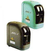
Laser plane builder BOIF APL-1
The main LPP manufacturers in Europe are Geo-Fennel, Stabila (Germany), Agatec (France), Zircon, Trimble (USA). Most LLPs sold in Russia under other brands are either copies of the products of these companies (in a different case or color) and are made to order (usually more expensive), or are made in China or Taiwan, often with lower build quality. But in China there are also high-quality devices. We are talking about the LLP, produced at the Beijing Optical and Mechanical Plant (BOIF) - APL-1, offered on the Russian market for a little more than 4100 rubles. It is made of high quality plastic and has a rubberized outer case that protects the device from falls. LLP can simultaneously project three lines - one horizontal and two vertical lines projected onto the walls at an angle of 90° relative to the center of the device's emitter. This device is used for simultaneous marking of two vertical walls located at an angle of 90 °. The APL-1 is one of the most affordable, and its driver is covered with a black plastic overlay with slots for beams in the form of a cross, which makes the glass less vulnerable to accidental bumps and drops than similar Triax LS series devices.
|
The laser beam projection sweep is limited by the pendulum and emitter lens mounting. This means that the laser plane projected in one direction is limited horizontally by a circle with an angle of 0-90° (depending on the model of the device) and can be increased using additional emitters located perpendicular to each other. When turning the device around its axis, it can lead to a displacement of the horizon if the LLP is not equipped with a special swivel mount with a limb and a fine-tuning knob, such as the FL-50 Multi-Linner and FL-50 Plus models of the German company Geo-Fennel. By the way, the latter gives a sweep with an approximate angle of 270° of the horizontal line and the vertical line, as well as 360° of the second vertical line located perpendicular to the first, which makes it practically inaccessible to competitors.
Laser square (right angle builder)
The laser square belongs to the category of plane builders with a fixed emitter and projects two lines at an angle of 90 ° relative to each other on the floor or wall (work surface). It is a good tool for controlling working axes and is widely represented on the Russian market by two models - the Square Linner of the German company Geo-Fennel and the LT-80 of the Triax company. Unfortunately, this device cannot replace plastic crosses that allow you to maintain the seams between tiles in the same dimension and is used only to control the working axes (it is installed for checking and then removed for the laying of the next tile many times during work). The LT-80 is too heavy (3.4kg) to constantly put, lift and retract for inspection, performs to a claimed 4mm accuracy at 10m, and is more than three times the price of the Square Linner (claimed 3mm accuracy at 10m). m), which makes the Geo-Fennel device more practical .
Multibeam laser tool
From the name of this group of laser builders, it is clear that these devices project laser dots onto the surface and are designed to mark holes that are perpendicular to each other on several surfaces at once. The most advanced models of this type use a system of five points: two vertical up and down from the device, two horizontal to the right and left, and one directly in front of the device, which allows you to mark any frame structure located to the right, left, top, bottom and in front of the device.
Multi-Pointer Laser Pointer
So far, there are three similar devices on the Russian market - RT-7610-5 (Robotoolz), PLS-5 (Pacific Laser System) and Multi-Pointer from Geo-Fennel. According to the declared characteristics, the most accurate is the German Multi-Pointer (Fig. 4), and the multifunctional mount included in its kit (allows you to mount the device to the wall, tripods with a 5/8 "or 1/4" screw, wooden surfaces on nails or metal when help of a magnet), bring it forward. It should be noted that with the price of analogues in the region of 12-13 thousand rubles, the price of the Multi-Pointer looks more attractive.

|
Laser level (full horizontal plane builder)
Laser builders of a horizontal or vertical plane with a projection radius of 360 ° are called levels, which have almost completely replaced the builders of planes from this segment of laser builders. After all, a laser builder with a compensator suspended inside can only give a horizontal projection, at the same time, almost any laser level can be used both in a horizontal and vertical position, often work in different modes (point, line and laser cut) and use it with receiver and/or remote control.
Laser level Agatec M-10
One of the latest builders on the Russian market is the builder PLS-360 (Pacific Laser System) with a cost of more than 14 thousand rubles today. Its direct competitor is the M-10 laser level of the French company Agatec. At a cost of less than 9 thousand rubles, this device can:
- be used to build both horizontal and vertical planes;
- work in the mode of a point, a closed line and a laser cut;
- be controlled from the remote control, which is included in the delivery;
- fasten on different surfaces and on a sling using the built-in multifunctional fastening;
- set an inclined plane;

|
The closest analogue of this level is an almost exact replica from Triax with the LT-60 model at a price almost 40% higher than the price of the French Agatec M-10.
How to choose a device
The most widely represented on the Russian market are the German companies Geo-Fennel, Stabila, the French company Agatec, the Beijing Optical and Mechanical Plant, which indicates a steady demand and high popularity for these manufacturers' LPs. When choosing a laser builder, the following aspects should be considered:
- It is necessary to fully and clearly define the tasks for which a laser builder is needed;
- Our consultants will help you with the search and processing of information about devices;
- Visit our showroom and see the device itself;
- Do not save on versatility at the expense of the quality of work;
- Do not buy devices of poor external performance from an unknown seller, you should give preference to well-known brands of equipment;
- Do not overpay extra money for a more expensive European device if there is an analogue manufactured by a well-known factory in China - this will save you money, allow you to learn how to work with the device and be a great gift to your friend when you are going to buy a more prestigious and advanced model of a European manufacturer.
- Check the error with which the device builds planes. Very often, especially for laser levels, high accuracy can lead to a limited number of functions;
- Keep in mind that devices that work with the receiver have a different wavelength emitter, which may cause a lighter beam of radiation.
- The laser beam is best seen in special glasses that can be purchased from a laser builder dealer, they will really help you in your work for the small remuneration that the supplier receives;
- Remember - accuracy is never superfluous! This will help you save time, money and nerves, as well as make a good impression on the customer.
Provided by OOO "Geo Total"
To indicate the position of the human body in space, the location of its parts relative to each other in anatomy, the concepts of planes and axes are used (Fig. 1). It is customary to consider the initial position of the body when a person is standing, legs together, palms facing forward. Man, like other vertebrates, is built on the principle of bilateral (bilateral) symmetry, his body is divided into two halves - right and left. The boundary between them is the median (median) plane, located vertically and oriented from front to back in the sagittal direction (from Latin sagitta - arrow). This plane is also called the sagittal plane.
Sagittal plane separates the right side of the body (right - dexter) from the left (left - sinister). The vertical plane, oriented perpendicular to the sagittal and separating the front part of the body (anterior - anterior) from the back (posterior - posterior), is called frontal (from Latin irons - forehead). This plane in its direction corresponds to the plane of the forehead.
As synonyms for the terms "anterior" and "posterior" in determining the position of the internal organs, the concepts of "abdominal" or "ventral" (ventralis) and "dorsal" or "dorsal" (dorsilis) can be used, respectively.
Rice. 1. Axes and planes drawn through the human body (diagram).
1 - vertical (longitudinal) axis;
2 - frontal plane;
3-horizontal plane;
4-transverse axis;
5-sagittal axis;
6-sagittal plane.
horizontal plane is oriented perpendicular to the sagittal and frontal and separates the lower parts of the body (lower - inferior) from the overlying ones (upper - superior).
These three planes - sagittal, frontal and horizontal - can be drawn through any point on the human body. Therefore, the number of planes can be arbitrary. According to the planes, directions (axes) can be distinguished that allow the organs to be oriented relative to the position of the body. The vertical axis (vertical - verticalis) is directed along the body of a standing person. Along this axis are the spinal column and the organs lying along it (spinal cord, thoracic and abdominal parts of the aorta, thoracic duct, esophagus). vertical axis coincides with the longitudinal axis (longitudinal - longitudinalis), which is also oriented along the human body, regardless of its position in space or along a limb (leg, arm), or along an organ, the long dimensions of which prevail over other dimensions. The frontal (transverse) axis (transverse - transversus, transversalis) coincides in direction with the frontal plane. This axis is oriented right to left or left to right. The sagittal axis (sagittal - sagittalis) is located in the anteroposterior direction, as is the sagittal plane.
To indicate the position of organs and parts of the body, the following definitions are used, which are included in the list of anatomical terms:
medial (medialis), if the organ (organs) lies closer to the median plane;
lateral (lateral; lateralis), if the organ is located further from the median plane;
intermediate (intermedins), if the organ lies between two adjacent formations;
internal (lying inside; internus) and external (lying outside; externus), when talking about organs located respectively inside, in the body cavity, or outside it;
deep (lying deeper; profundus) and superficial (located on the surface; superficialis) to determine the position of organs lying at different depths.
When describing the upper and lower limbs, special terms are used. To indicate the beginning of the limb - the part that is closer to the body, use the definition of proximal (closest to the body) (rgoximalis). The part of the limb remote from the body is called distal (distalis). The surface of the upper limb relative to the palm is designated by the term palmar (palmaris or volaris - located on the side of the palm), and the lower limb
Ti relative to the sole - plantar (plantaris). The edge of the forearm from the side of the radius is called the radius (radialis), and from the side of the ulna - the ulna (ulnaris). On the lower leg, the edge where the fibula is located is called the fibula (fibularis), and the opposite edge, where the tibia lies, is called the tibia (tibialis).
To determine the projection of the boundaries of the heart, lungs, liver, pleura and other organs, vertical lines are conventionally drawn on the surface of the body, oriented along the human body. The anterior median line (linea mediana anterior) runs along the front surface of the human body, on the border between its right and left halves. The posterior median line (linea mediana posterior) runs along the spinal column, above the tops of the spinous processes of the vertebrae. Between these two lines on each side, several more conditional lines can be drawn through the anatomical formations on the surface of the body. The sternal line (linea sternalis) runs along the edge of the sternum, the mid-clavicular line (linea medioclaviculdris) passes through the middle of the clavicle. Often this line coincides with the position of the nipple of the mammary gland, in connection with which it is also called the nipple line (linea mamillaris). The anterior axillary line (linea axillaris anterior) starts from the fold of the same name (plica axillaris anterior) in the axillary fossa and runs along the body.
The middle axillary line (linea axillaris media) starts from the deepest point of the axillary fossa; posterior axillary line (linea axillaris posterior) - from the fold of the same name (plica axillaris posterior). The scapular line (linea scapularis) passes through the lower angle of the scapula, the paravertebral line (linea paravertebralis) - along the spinal column through the costal-transverse joints (transverse processes of the vertebrae).
Read also...
- The height and diameter of the chimney for solid fuel boilers Calculation of the chimney from the boiler in a private house
- How to properly make a roof vapor barrier: technological principles of a vapor barrier device
- Chimney for a gas boiler: device features and requirements for gas boilers What pipe diameter is needed for a gas boiler
- Mansard roofs: types and design features


